
熟悉RT-Thread的朋友都知道,RT-Thread提供了许多BSP,但不是所有的板子都能找到相应的BSP,这时就需要移植新的BSP。RT-Thread的所有BSP中,最完善的BSP就是STM32系列,但从2020年下半年开始,国内出现史无前例的芯片缺货潮,芯片的交期和价格不断拉升,STM32的价格也是水涨船高,很多朋友也在考虑使用国产替代,笔者使用的兆易创新的GD32系列,我看了下RT-Thread中GD系列BSP,都是玩家各自为政,每个人都是提交自己使用的板子的BSP,充斥着大量冗余的代码,对于有强迫症的我就非常不爽,就根据手头的板子,参看STM32的BSP架构,构建了GD32的BSP架构。
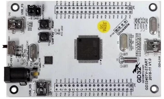
笔者使用的开发板是兆易创新设计的GD32407V-START开发板。其主控芯片为GD32F407VKT6,主频168MHz,内部3072K Flash,192KB SRAM,资源相当丰富。
1 BSP 框架制作
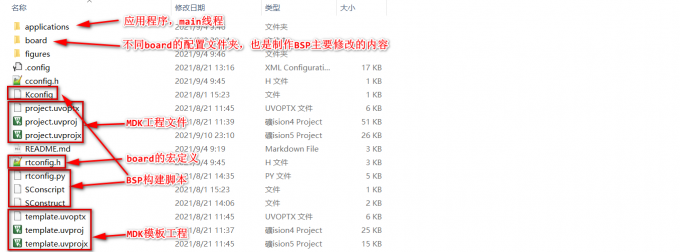
在具体移植GD32407V-START的BSP之前,先做好GD32的BSP架构。BSP 框架结构如下图所示:
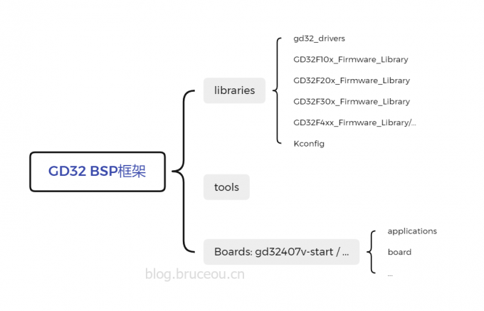
GD32的BSP架构主要分为三个部分:libraries、tools和具体的Boards,其中libraries包含了GD32的通用库,包括每个系列的HAL以及适配RT-Thread的drivers;tools是生成工程的Python脚本工具;另外就是Boards文件,当然这里的Boards有很多,我这里值列举了GD32407V-START。
这里先谈谈libraries和tools的构建,然后在后文单独讨论具体板级BSP的制作。
1.1 Libraries构建
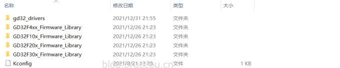
Libraries文件夹包含兆易创新提供的HAL库,这个直接在兆易创新的官网就可以下载。
然后将GD32F4xx_Firmware_Library库复制到libraries目录下,其他的系列类似。
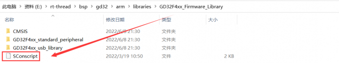
GD32F4xx_Firmware_Library就是官方的文件,基本是不用动的,只是在文件夹中需要添加构建工程的脚本文件SConscript,其实也就是Python脚本。
SConscript文件的内容如下:
import rtconfig #导包
from building import *

# get current directory
cwd = GetCurrentDir() #获取当然路径

# The set of source files associated with this SConscript file.

src = Split('''
CMSIS/GD/GD32F4xx/Source/system_gd32f4xx.c
GD32F4xx_standard_peripheral/Source/gd32f4xx_gpio.c
GD32F4xx_standard_peripheral/Source/gd32f4xx_rcu.c
GD32F4xx_standard_peripheral/Source/gd32f4xx_exti.c
GD32F4xx_standard_peripheral/Source/gd32f4xx_misc.c
GD32F4xx_standard_peripheral/Source/gd32f4xx_syscfg.c
''')#将括号中的字符串分割后成列表(list),以便包含到工程中

if GetDepend(['RT_USING_SERIAL']):#如果打开了RT_USING_SERIAL的宏,则会包含以下源文件
    src += ['GD32F4xx_standard_peripheral/Source/gd32f4xx_usart.c']

if GetDepend(['RT_USING_I2C']):
    src += ['GD32F4xx_standard_peripheral/Source/gd32f4xx_i2c.c']

if GetDepend(['RT_USING_SPI']):
    src += ['GD32F4xx_standard_peripheral/Source/gd32f4xx_spi.c']

if GetDepend(['RT_USING_CAN']):
    src += ['GD32F4xx_standard_peripheral/Source/gd32f4xx_can.c']

if GetDepend(['BSP_USING_ETH']):
    src += ['GD32F4xx_standard_peripheral/Source/gd32f4xx_enet.c']

if GetDepend(['RT_USING_ADC']):
    src += ['GD32F4xx_standard_peripheral/Source/gd32f4xx_adc.c']

if GetDepend(['RT_USING_DAC']):
    src += ['GD32F4xx_standard_peripheral/Source/gd32f4xx_dac.c']

if GetDepend(['RT_USING_RTC']):
    src += ['GD32F4xx_standard_peripheral/Source/gd32f4xx_rtc.c']

if GetDepend(['RT_USING_WDT']):
    src += ['GD32F4xx_standard_peripheral/Source/gd32f4xx_wwdgt.c']
    src += ['GD32F4xx_standard_peripheral/Source/gd32f4xx_fwdgt.c']

if GetDepend(['RT_USING_SDIO']):
    src += ['GD32F4xx_standard_peripheral/Source/gd32f4xx_sdio.c']

#头文件路径
path = [
    cwd + '/CMSIS/GD/GD32F4xx/Include',
    cwd + '/CMSIS',
    cwd + '/GD32F4xx_standard_peripheral/Include',]

CPPDEFINES = ['USE_STDPERIPH_DRIVER']
#定义一个组,组名为'Libraries', depend为空表示依赖任何一个其他宏,另外当前的头文件路径添加到工程中
group = DefineGroup('Libraries', src, depend = [''], CPPPATH = path, CPPDEFINES = CPPDEFINES)

Return('group')
该文件主要的作用就是添加库文件和头文件路径,一部分文件是属于基础文件,因此直接调用Python库的Split包含,另外一部分文件是根据实际的应用需求添加的。
这里是以GD32F4来举例的,其他系列的都是类似的。
接下来说说Kconfig文件,这里是对内核和组件的功能进行配置,对RT-Thread的组件进行自由裁剪。
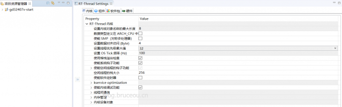
如果使用RT-Thread studio,则通过RT-Thread Setting可以体现Kconfig文件的作用。
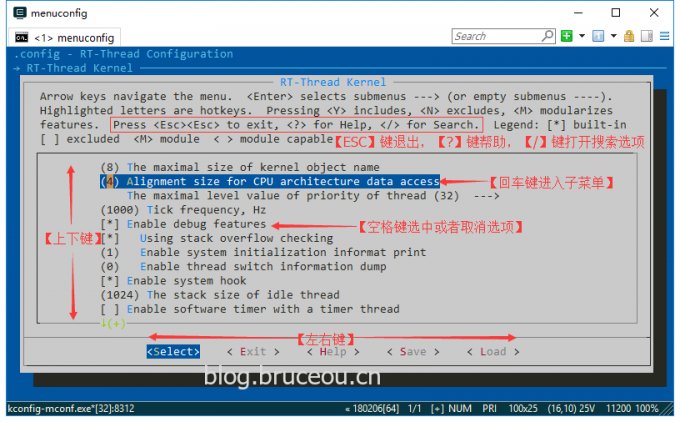
如果使用ENV环境,则在使用 menuconfig配置和裁剪 RT-Thread时体现。
后面所有的Kconfig文件都是一样的逻辑。下表列举一些常用的Kconfig句法规则。
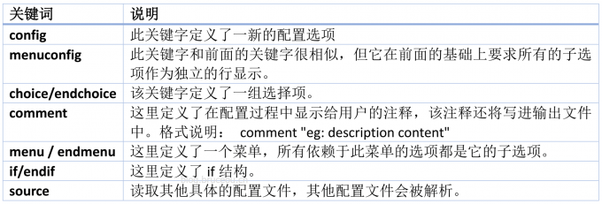
Kconfig的语法规则网上资料很多,自行去学习吧。
bsp/gd32/Kconfig内容如下:
config SOC_FAMILY_GD32
    bool

config SOC_SERIES_GD32F4
    bool
    select ARCH_ARM_CORTEX_M4
    select SOC_FAMILY_GD32
因为该架构目前笔者只移植了GDF4的,因此这里的内容比较少,如果有些的系列,直接参考F4的配置例子在这里加就可以了。
最后谈谈gd32_drivers,这个文件夹就是GD32的外设驱动文件夹,为上层应用提供调用接口。
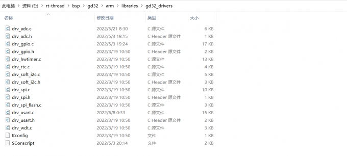
该文件夹是整个GD32共用的,因此在编写和修改都要慎重。关于drv_xxx文件在后句具体移植BSP的时候讲解,这里主要将整体架构,SConscript和Kconfig的作用和前面的一样,只是具体的内容不同罢了。
好了,先看bsp/gd32/gd32_drivers/SConscript文件。
import('RTT_ROOT')
import('rtconfig')
from building import *

cwd = GetCurrentDir()

# add the general drivers.
src = Split("""
""")

# add pin drivers.
if GetDepend('RT_USING_PIN'):
    src += ['drv_gpio.c']

# add usart drivers.
if GetDepend(['RT_USING_SERIAL']):
    src += ['drv_usart.c']

# add adc drivers.
if GetDepend('RT_USING_ADC'):
    src += ['drv_adc.c']

# add i2c drivers.
if GetDepend(['RT_USING_I2C', 'RT_USING_I2C_BITOPS']):
    if GetDepend('BSP_USING_I2C0') or GetDepend('BSP_USING_I2C1') or GetDepend('BSP_USING_I2C2') or GetDepend('BSP_USING_I2C3'):
        src += ['drv_soft_i2c.c']

# add spi drivers.
if GetDepend('RT_USING_SPI'):
    src += ['drv_spi.c']

# add spi flash drivers.
if GetDepend('RT_USING_SFUD'):
    src += ['drv_spi_flash.c', 'drv_spi.c']

# add hwtimer drivers.
if GetDepend('RT_USING_HWTIMER'):
    src += ['drv_hwtimer.c']

# add rtc drivers.
if GetDepend('RT_USING_RTC'):
    src += ['drv_rtc.c']

# add iwdt drivers.
if GetDepend('RT_USING_WDT'):
    src += ['drv_iwdt.c']

path =  [cwd]

group = DefineGroup('Drivers', src, depend = [''], CPPPATH = path)

Return('group')
和GD32F4xx_Firmware_Library文件夹中的SConscript是类似的。
bsp/gd32/gd32_drivers/Kconfig文件结构如下:
if BSP_USING_USBD
    config BSP_USBD_TYPE_FS
        bool
        # "USB Full Speed (FS) Core"
    config BSP_USBD_TYPE_HS
        bool
        # "USB High Speed (HS) Core"

    config BSP_USBD_SPEED_HS
        bool
        # "USB High Speed (HS) Mode"
    config BSP_USBD_SPEED_HSINFS
        bool
        # "USB High Speed (HS) Core in FS mode"

    config BSP_USBD_PHY_EMBEDDED
        bool
        # "Using Embedded phy interface"
    config BSP_USBD_PHY_UTMI
        bool
        # "UTMI: USB 2.0 Transceiver Macrocell Interace"
    config BSP_USBD_PHY_ULPI
        bool
        # "ULPI: UTMI+ Low Pin Interface"
endif
1.2 Tools构建
该文件夹就是工程构建的脚本,
import os
import sys
import shutil

cwd_path = os.getcwd()
sys.path.append(os.path.join(os.path.dirname(cwd_path), 'rt-thread', 'tools'))

def bsp_update_board_kconfig(dist_dir):
    # change board/kconfig path
    if not os.path.isfile(os.path.join(dist_dir, 'board/Kconfig')):
        return

    with open(os.path.join(dist_dir, 'board/Kconfig'), 'r') as f:
        data = f.readlines()
    with open(os.path.join(dist_dir, 'board/Kconfig'), 'w') as f:
        for line in data:
            if line.find('../libraries/gd32_drivers/Kconfig') != -1:
                position = line.find('../libraries/gd32_drivers/Kconfig')
                line = line[0:position] + 'libraries/gd32_drivers/Kconfig"\n'
            f.write(line)

# BSP dist function
def dist_do_building(BSP_ROOT, dist_dir):
    from mkdist import bsp_copy_files
    import rtconfig

    print("=> copy gd32 bsp library")
    library_dir = os.path.join(dist_dir, 'libraries')
    library_path = os.path.join(os.path.dirname(BSP_ROOT), 'libraries')
    bsp_copy_files(os.path.join(library_path, rtconfig.BSP_LIBRARY_TYPE),
                   os.path.join(library_dir, rtconfig.BSP_LIBRARY_TYPE))

    print("=> copy bsp drivers")
    bsp_copy_files(os.path.join(library_path, 'gd32_drivers'), os.path.join(library_dir, 'gd32_drivers'))
    shutil.copyfile(os.path.join(library_path, 'Kconfig'), os.path.join(library_dir, 'Kconfig'))

    bsp_update_board_kconfig(dist_dir)
以上代码很简单,主要使用了Python的OS模块的join函数,该函数的作用就是连接两个或更多的路径名。最后将BSP依赖的文件复制到指定目录下。
在使用scons –dist 命令打包的时候,就是依赖的该脚本,生成的dist 文件夹的工程到任何目录下使用,也就是将BSP相关的库以及内核文件提取出来,可以将该工程任意拷贝。
需要注意的是,使用scons –dist打包后需要修改board/Kconfig中的库路径,因此这里调用了bsp_update_board_kconfig方法修改。
1.3 gd32407v-start构建
该文件夹就gd32407v-start的具体BSP文件,文件结构如下:
在后面将具体讲解如何构建该部分内容。
2 BSP移植
2.1 Keil环境准备
目前市面通用的MDK for ARM版本有Keil 4和Keil 5:使用Keil 4建议安装4.74及以上;使用Keil 5建议安装5.20以上版本。笔者的MDK是5.30。
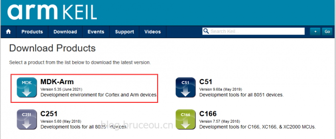
从MDK的官网可以下载得到MDK的安装包,然后安装即可,关于的MDK安装请看笔者的教程。
MDK安装教程:https://blog.csdn.net/bruceoxl/article/details/108548573
MDK下载地址:https://www.keil.com/download/product/
安装完成后会自动打开,我们将其关闭。
接下来我们下载GD32F30x的软件支持包。
下载地址:http://www.gd32mcu.com/cn/download
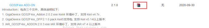
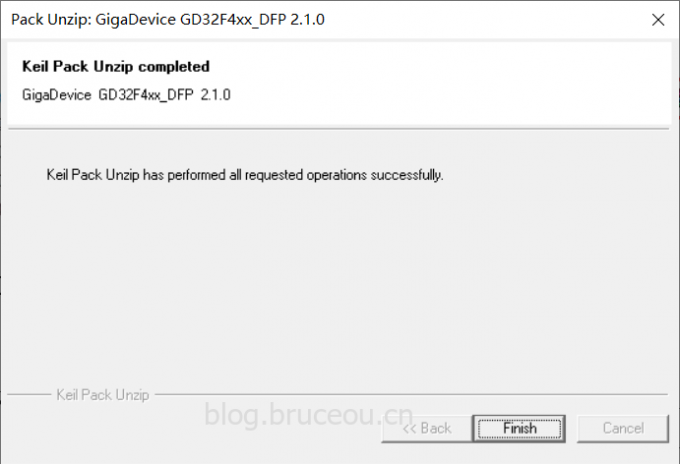
下载好后双击GigaDevice.GD32F4xx_DFP.2.1.0.pack运行即可:
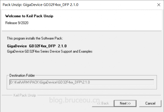
点击[Next]即可安装完成。
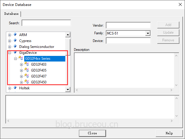
安装成功后,重新打开Keil,则可以在File->Device Database中出现Gigadevice的下拉选项,点击可以查看到相应的型号。
2.2 BSP工程制作
1.构建基础工程
首先看看RT-Thread代码仓库中已有很多BSP,而我要移植的是Cortex-M4内核。这里我找了一个相似的内核,把它复制一份,并修改文件名为:gd32407v-start。这样就有一个基础的工程。然后就开始增删改查,完成最终的BSP,几乎所有的BSP的制作都是如此。
2.修改BSP构建脚本
bsp/gd32/gd32407v-start/SConstruct修改后的内容如下:
import os
import sys
import rtconfig

if os.getenv('RTT_ROOT'):
    RTT_ROOT = os.getenv('RTT_ROOT')
else:
    RTT_ROOT = os.path.normpath(os.getcwd() + '/../../../..')

sys.path = sys.path + [os.path.join(RTT_ROOT, 'tools')]
try:
    from building import *
except:
    print('Cannot found RT-Thread root directory, please check RTT_ROOT')
    print(RTT_ROOT)
    exit(-1)

TARGET = 'rtthread.' + rtconfig.TARGET_EXT

DefaultEnvironment(tools=[])
env = Environment(tools = ['mingw'],
    AS = rtconfig.AS, ASFLAGS = rtconfig.AFLAGS,
    CC = rtconfig.CC, CCFLAGS = rtconfig.CFLAGS,
    AR = rtconfig.AR, ARFLAGS = '-rc',
    CXX = rtconfig.CXX, CXXFLAGS = rtconfig.CXXFLAGS,
    LINK = rtconfig.LINK, LINKFLAGS = rtconfig.LFLAGS)
env.PrependENVPath('PATH', rtconfig.EXEC_PATH)

if rtconfig.PLATFORM == 'iar':
    env.Replace(CCCOM = ['$CC $CCFLAGS $CPPFLAGS $_CPPDEFFLAGS $_CPPINCFLAGS -o $TARGET $SOURCES'])
    env.Replace(ARFLAGS = [''])
    env.Replace(LINKCOM = env["LINKCOM"] + ' --map rtthread.map')

Export('RTT_ROOT')
Export('rtconfig')

SDK_ROOT = os.path.abspath('./')

if os.path.exists(SDK_ROOT + '/libraries'):
    libraries_path_prefix = SDK_ROOT + '/libraries'
else:
    libraries_path_prefix = os.path.dirname(SDK_ROOT) + '/libraries'

SDK_LIB = libraries_path_prefix
Export('SDK_LIB')

# prepare building environment
objs = PrepareBuilding(env, RTT_ROOT, has_libcpu=False)

gd32_library = 'GD32F4xx_Firmware_Library'
rtconfig.BSP_LIBRARY_TYPE = gd32_library

# include libraries
objs.extend(SConscript(os.path.join(libraries_path_prefix, gd32_library, 'SConscript')))

# include drivers
objs.extend(SConscript(os.path.join(libraries_path_prefix, 'HAL_Drivers', 'SConscript')))

# make a building
DoBuilding(TARGET, objs)
该文件用于链接所有的依赖文件,并调用make进行编译。
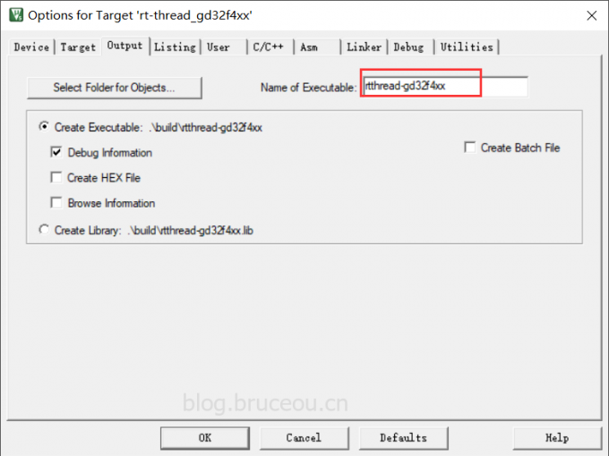
3.修改KEIL的模板工程
双击:template.uvprojx即可修改模板工程。
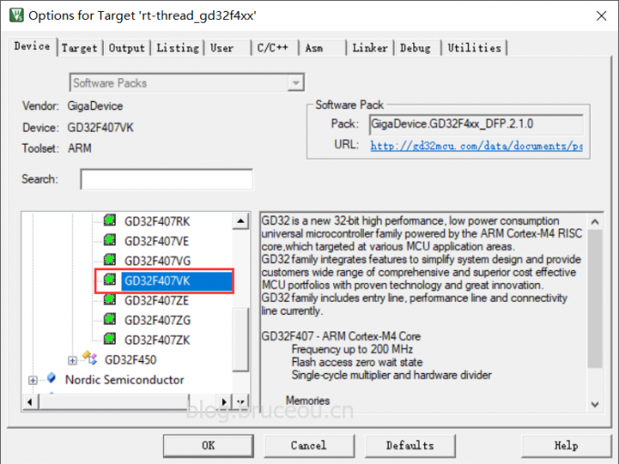
修改为对应芯片设备:
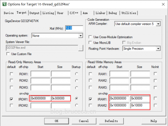
修改FLASH和RAM的配置:
修改可执行文件名字:
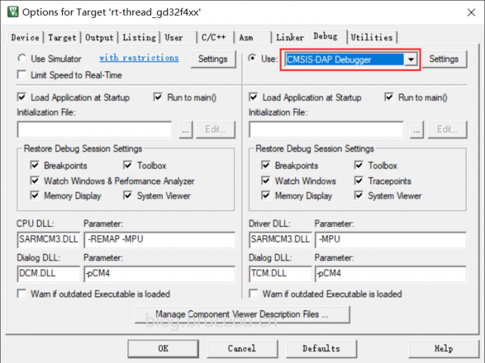
修改默认调试工具:CMSIS-DAP Debugger。
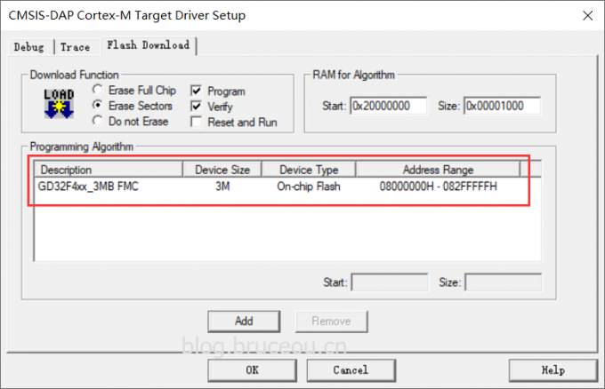
修改编程算法:GD32F4xx FMC。
4.修改board文件夹
(1) 修改bsp/gd32/arm/gd32407v-start/board/linker_scripts/link.icf
修改后的内容如下:
/*###ICF### Section handled by ICF editor, don't touch! ****/
/*-Editor annotation file-*/
/* IcfEditorFile="$TOOLKIT_DIR$\config\ide\IcfEditor\cortex_v1_0.xml" */
/*-Specials-*/
define symbol __ICFEDIT_intvec_start__ = 0x08000000;
/*-Memory Regions-*/
define symbol __ICFEDIT_region_ROM_start__ = 0x08000000;
define symbol __ICFEDIT_region_ROM_end__   = 0x082FFFFF;
define symbol __ICFEDIT_region_RAM_start__ = 0x20000000;
define symbol __ICFEDIT_region_RAM_end__   = 0x2002FFFF;
/*-Sizes-*/
define symbol __ICFEDIT_size_cstack__ = 0x2000;
define symbol __ICFEDIT_size_heap__   = 0x2000;
/**** End of ICF editor section. ###ICF###*/

export symbol __ICFEDIT_region_RAM_end__;

define symbol __region_RAM1_start__ = 0x10000000;
define symbol __region_RAM1_end__   = 0x1000FFFF;

define memory mem with size = 4G;
define region ROM_region   = mem:[from __ICFEDIT_region_ROM_start__   to __ICFEDIT_region_ROM_end__];
define region RAM_region   = mem:[from __ICFEDIT_region_RAM_start__   to __ICFEDIT_region_RAM_end__];
define region RAM1_region  = mem:[from __region_RAM1_start__   to __region_RAM1_end__];

define block CSTACK    with alignment = 8, size = __ICFEDIT_size_cstack__   { };
define block HEAP      with alignment = 8, size = __ICFEDIT_size_heap__     { };

initialize by copy { readwrite };
do not initialize  { section .noinit };

keep { section FSymTab };
keep { section VSymTab };
keep { section .rti_fn* };
place at address mem:__ICFEDIT_intvec_start__ { readonly section .intvec };

place in ROM_region   { readonly };
place in RAM_region   { readwrite,
                        block CSTACK, block HEAP };
place in RAM1_region  { section .sram };
该文件是IAR编译的链接脚本,根据《GD32F407xx_Datasheet_Rev2.1》可知,GD32F407VKT6的flash大小为3072KB,SRAM大小为192KB,因此需要设置ROM和RAM的起始地址和堆栈大小等。
(2) 修改bsp/gd32/arm/gd32407v-start/board/linker_scripts/link.ld
修改后的内容如下:
/* Program Entry, set to mark it as "used" and avoid gc */
MEMORY
{
    CODE (rx) : ORIGIN = 0x08000000, LENGTH = 3072k /* 3072KB flash */
    DATA (rw) : ORIGIN = 0x20000000, LENGTH =  192k /* 192KB sram */
}
ENTRY(Reset_Handler)
_system_stack_size = 0x200;

SECTIONS
{
    .text :
    {
        . = ALIGN(4);
        _stext = .;
        KEEP(*(.isr_vector))            /* Startup code */
        . = ALIGN(4);
        *(.text)                        /* remaining code */
        *(.text.*)                      /* remaining code */
        *(.rodata)                      /* read-only data (constants) */
        *(.rodata*)
        *(.glue_7)
        *(.glue_7t)
        *(.gnu.linkonce.t*)

        /* section information for finsh shell */
        . = ALIGN(4);
        __fsymtab_start = .;
        KEEP(*(FSymTab))
        __fsymtab_end = .;
        . = ALIGN(4);
        __vsymtab_start = .;
        KEEP(*(VSymTab))
        __vsymtab_end = .;
        . = ALIGN(4);

        /* section information for initial. */
        . = ALIGN(4);
        __rt_init_start = .;
        KEEP(*(SORT(.rti_fn*)))
        __rt_init_end = .;
        . = ALIGN(4);

        . = ALIGN(4);
        _etext = .;
    } > CODE = 0

    /* .ARM.exidx is sorted, so has to go in its own output section.  */
    __exidx_start = .;
    .ARM.exidx :
    {
        *(.ARM.exidx* .gnu.linkonce.armexidx.*)

        /* This is used by the startup in order to initialize the .data secion */
        _sidata = .;
    } > CODE
    __exidx_end = .;

    /* .data section which is used for initialized data */

    .data : AT (_sidata)
    {
        . = ALIGN(4);
        /* This is used by the startup in order to initialize the .data secion */
        _sdata = . ;

        *(.data)
        *(.data.*)
        *(.gnu.linkonce.d*)

        . = ALIGN(4);
        /* This is used by the startup in order to initialize the .data secion */
        _edata = . ;
    } >DATA

    .stack :
    {
        . = . + _system_stack_size;
        . = ALIGN(4);
        _estack = .;
    } >DATA

    __bss_start = .;
    .bss :
    {
        . = ALIGN(4);
        /* This is used by the startup in order to initialize the .bss secion */
        _sbss = .;

        *(.bss)
        *(.bss.*)
        *(COMMON)

        . = ALIGN(4);
        /* This is used by the startup in order to initialize the .bss secion */
        _ebss = . ;

        *(.bss.init)
    } > DATA
    __bss_end = .;

    _end = .;

    /* Stabs debugging sections.  */
    .stab          0 : { *(.stab) }
    .stabstr       0 : { *(.stabstr) }
    .stab.excl     0 : { *(.stab.excl) }
    .stab.exclstr  0 : { *(.stab.exclstr) }
    .stab.index    0 : { *(.stab.index) }
    .stab.indexstr 0 : { *(.stab.indexstr) }
    .comment       0 : { *(.comment) }
    /* DWARF debug sections.
     * Symbols in the DWARF debugging sections are relative to the beginning
     * of the section so we begin them at 0.  */
    /* DWARF 1 */
    .debug          0 : { *(.debug) }
    .line           0 : { *(.line) }
    /* GNU DWARF 1 extensions */
    .debug_srcinfo  0 : { *(.debug_srcinfo) }
    .debug_sfnames  0 : { *(.debug_sfnames) }
    /* DWARF 1.1 and DWARF 2 */
    .debug_aranges  0 : { *(.debug_aranges) }
    .debug_pubnames 0 : { *(.debug_pubnames) }
    /* DWARF 2 */
    .debug_info     0 : { *(.debug_info .gnu.linkonce.wi.*) }
    .debug_abbrev   0 : { *(.debug_abbrev) }
    .debug_line     0 : { *(.debug_line) }
    .debug_frame    0 : { *(.debug_frame) }
    .debug_str      0 : { *(.debug_str) }
    .debug_loc      0 : { *(.debug_loc) }
    .debug_macinfo  0 : { *(.debug_macinfo) }
    /* SGI/MIPS DWARF 2 extensions */
    .debug_weaknames 0 : { *(.debug_weaknames) }
    .debug_funcnames 0 : { *(.debug_funcnames) }
    .debug_typenames 0 : { *(.debug_typenames) }
    .debug_varnames  0 : { *(.debug_varnames) }
}
该文件是GCC编译的链接脚本,根据《GD32F407xx_Datasheet_Rev2.1》可知,GD32F407VKT6的flash大小为3072KB,SRAM大小为192KB,因此CODE和DATA 的LENGTH分别设置为3072KB和192KB,其他芯片类似,但其实地址都是一样的。
(3) 修改bsp/gd32/arm/gd32407v-start/board/linker_scripts/link.sct
该文件是MDK的连接脚本,根据《GD32F407xx_Datasheet_Rev2.1》手册,因此需要将 LR_IROM1 和 ER_IROM1 的参数设置为 0x00300000;RAM 的大小为192k,因此需要将 RW_IRAM1 的参数设置为 0x00030000。
; *************************************************************
; *** Scatter-Loading Description File generated by uVision ***
; *************************************************************

LR_IROM1 0x08000000 0x00300000  {    ; load region size_region
  ER_IROM1 0x08000000 0x00300000  {  ; load address = execution address
   *.o (RESET, +First)
   *(InRoot$$Sections)
   .ANY (+RO)
  }
  RW_IRAM1 0x20000000 0x00030000  {  ; RW data
   .ANY (+RW +ZI)
  }
}
(4) 修改bsp/gd32/arm/gd32407v-start/board/board.h文件
修改后内容如下:
#ifndef __BOARD_H__
#define __BOARD_H__

#include "gd32f4xx.h"
#include "drv_usart.h"
#include "drv_gpio.h"

#include "gd32f4xx_exti.h"

#define EXT_SDRAM_BEGIN    (0xC0000000U) /* the begining address of external SDRAM */
#define EXT_SDRAM_END      (EXT_SDRAM_BEGIN + (32U * 1024 * 1024)) /* the end address of external SDRAM */

// <o> Internal SRAM memory size[Kbytes] <8-64>
//  <i>Default: 64
#ifdef __ICCARM__
// Use *.icf ram symbal, to avoid hardcode.
extern char __ICFEDIT_region_RAM_end__;
#define GD32_SRAM_END          &__ICFEDIT_region_RAM_end__
#else
#define GD32_SRAM_SIZE         192
#define GD32_SRAM_END          (0x20000000 + GD32_SRAM_SIZE * 1024)
#endif

#ifdef __CC_ARM
extern int Image$$RW_IRAM1$$ZI$$Limit;
#define HEAP_BEGIN    (&Image$$RW_IRAM1$$ZI$$Limit)
#elif __ICCARM__
#pragma section="HEAP"
#define HEAP_BEGIN    (__segment_end("HEAP"))
#else
extern int __bss_end;
#define HEAP_BEGIN    (&__bss_end)
#endif

#define HEAP_END          GD32_SRAM_END

#endif
值得注意的是,不同的编译器规定的堆栈内存的起始地址 HEAP_BEGIN 和结束地址 HEAP_END。这里 HEAP_BEGIN 和 HEAP_END 的值需要和前面的链接脚本是一致的,需要结合实际去修改。
(5) 修改bsp/gd32/arm/gd32407v-start/board/board.c文件
修改后的文件如下:
#include <stdint.h>
#include <rthw.h>
#include <rtthread.h>
#include <board.h>

/**
  * @brief  This function is executed in case of error occurrence.
  * @param  None
  * @retval None
  */
void Error_Handler(void)
{
    /* USER CODE BEGIN Error_Handler */
    /* User can add his own implementation to report the HAL error return state */
    while (1)
    {
    }
    /* USER CODE END Error_Handler */
}

/** System Clock Configuration
*/
void SystemClock_Config(void)
{
    SysTick_Config(SystemCoreClock / RT_TICK_PER_SECOND);
    NVIC_SetPriority(SysTick_IRQn, 0);
}

/**
 * This is the timer interrupt service routine.
 *
 */
void SysTick_Handler(void)
{
    /* enter interrupt */
    rt_interrupt_enter();

    rt_tick_increase();

    /* leave interrupt */
    rt_interrupt_leave();
}

/**
 * This function will initial GD32 board.
 */
void rt_hw_board_init()
{
    /* NVIC Configuration */
#define NVIC_VTOR_MASK              0x3FFFFF80
#ifdef  VECT_TAB_RAM
    /* Set the Vector Table base location at 0x10000000 */
    SCB->VTOR  = (0x10000000 & NVIC_VTOR_MASK);
#else  /* VECT_TAB_FLASH  */
    /* Set the Vector Table base location at 0x08000000 */
    SCB->VTOR  = (0x08000000 & NVIC_VTOR_MASK);
#endif

    SystemClock_Config();

#ifdef RT_USING_COMPONENTS_INIT
    rt_components_board_init();
#endif

#ifdef RT_USING_CONSOLE
    rt_console_set_device(RT_CONSOLE_DEVICE_NAME);
#endif

#ifdef BSP_USING_SDRAM
    rt_system_heap_init((void *)EXT_SDRAM_BEGIN, (void *)EXT_SDRAM_END);
#else
    rt_system_heap_init((void *)HEAP_BEGIN, (void *)HEAP_END);
#endif
}
该文件重点关注的就是SystemClock_Config配置,SystemCoreClock的定义在system_gd32f4xx.c中定义的。
(6) 修改bsp/gd32/arm/gd32407v-start/board/Kconfig文件
修改后内容如下:
menu "Hardware Drivers Config"

config SOC_GD32407V
    bool
    select SOC_SERIES_GD32F4
    select RT_USING_COMPONENTS_INIT
    select RT_USING_USER_MAIN
    default y

menu "Onboard Peripheral Drivers"

endmenu

menu "On-chip Peripheral Drivers"

    config BSP_USING_GPIO
        bool "Enable GPIO"
        select RT_USING_PIN
        default y

    menuconfig BSP_USING_UART
        bool "Enable UART"
        default y
        select RT_USING_SERIAL
        if BSP_USING_UART
            config BSP_USING_UART1
                bool "Enable UART1"
                default y

            config BSP_UART1_RX_USING_DMA
                bool "Enable UART1 RX DMA"
                depends on BSP_USING_UART1 && RT_SERIAL_USING_DMA
                default n
        endif

    menuconfig BSP_USING_SPI
        bool "Enable SPI BUS"
        default n
        select RT_USING_SPI
        if BSP_USING_SPI
            config BSP_USING_SPI1
                bool "Enable SPI1 BUS"
                default n

            config BSP_SPI1_TX_USING_DMA
                bool "Enable SPI1 TX DMA"
                depends on BSP_USING_SPI1
                default n

            config BSP_SPI1_RX_USING_DMA
                bool "Enable SPI1 RX DMA"
                depends on BSP_USING_SPI1
                select BSP_SPI1_TX_USING_DMA
                default n
        endif

    menuconfig BSP_USING_I2C1
        bool "Enable I2C1 BUS (software simulation)"
        default n
        select RT_USING_I2C
        select RT_USING_I2C_BITOPS
        select RT_USING_PIN
        if BSP_USING_I2C1
            config BSP_I2C1_SCL_PIN
                int "i2c1 scl pin number"
                range 1 216
                default 24
            config BSP_I2C1_SDA_PIN
                int "I2C1 sda pin number"
                range 1 216
                default 25
        endif
    source "../libraries/gd32_drivers/Kconfig"

endmenu

menu "Board extended module Drivers"

endmenu

endmenu
这个文件就是配置板子驱动的,这里可根据实际需求添加。
(7) 修改bsp/gd32/arm/gd32407v-start/board/SConscript文件
修改后内容如下:
import os
import rtconfig
from building import *

Import('SDK_LIB')

cwd = GetCurrentDir()

# add general drivers
src = Split('''
board.c
''')

path =  [cwd]

startup_path_prefix = SDK_LIB

if rtconfig.CROSS_TOOL == 'gcc':
    src += [startup_path_prefix + '/GD32F4xx_HAL/CMSIS/GD/GD32F4xx/Source/GCC/startup_gd32f4xx.S']
elif rtconfig.CROSS_TOOL == 'keil':
    src += [startup_path_prefix + '/GD32F4xx_HAL/CMSIS/GD/GD32F4xx/Source/ARM/startup_gd32f4xx.s']
elif rtconfig.CROSS_TOOL == 'iar':
    src += [startup_path_prefix + '/GD32F4xx_HAL/CMSIS/GD/GD32F4xx/Source/IAR/startup_gd32f4xx.s']

CPPDEFINES = ['GD32F407']
group = DefineGroup('Drivers', src, depend = [''], CPPPATH = path, CPPDEFINES = CPPDEFINES)

Return('group')
该文件主要添加board文件夹的.c文件和头文件路径。另外根据开发环境选择相应的汇编文件,和前面的libraries的SConscript语法是一样,文件的结构都是类似的,这里就没有注释了。
到这里,基本所有的依赖脚本都配置完成了,接下来将通过menuconfig配置工程。
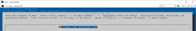
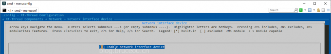
5.menuconfig配置
关闭套接字抽象层。
关闭网络设备接口。
关闭LWIP协议栈。
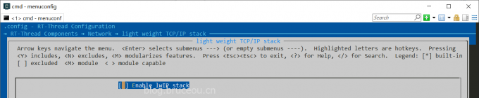
GD32407V-START板载没有以太网,因此这里主要是关闭网络相关的内容,当然GD32407V-START的资源丰富,不关这些其实也不影响,如果是其他MCU,根据实际需求自行修改吧。
6.驱动修改
一个基本的BSP中,串口是必不可少的,所以还需要编写串口驱动,这里使用的串口2作为调试串口。
板子上还有LED灯,主要要编写GPIO驱动即可。
关于串口和LED的驱动可以查看源码,这里就不贴出来了。
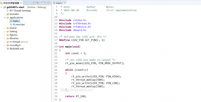
7.应用开发
笔者在applications的main.c中添加LED的应用代码,
#include <stdio.h>
#include <rtthread.h>
#include <rtdevice.h>
#include <board.h>

/* defined the LED2 pin: PC6 */
#define LED2_PIN GET_PIN(C, 6)

int main(void)
{
    int count = 1;

    /* set LED2 pin mode to output */
    rt_pin_mode(LED2_PIN, PIN_MODE_OUTPUT);

    while (count++)
    {
        rt_pin_write(LED2_PIN, PIN_HIGH);
        rt_thread_mdelay(500);
        rt_pin_write(LED2_PIN, PIN_LOW);
        rt_thread_mdelay(500);
    }

    return RT_EOK;
}
当然,这需要GPIO驱动的支持。
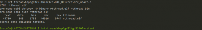
8.使用ENV编译工程
在env中执行:scons
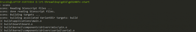
编译成功打印信息如下:
9.使用env生成MDK工程
在env中执行:scons –target=mdk5
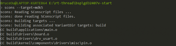
生成MDK工程后,打开MDK工程进行编译
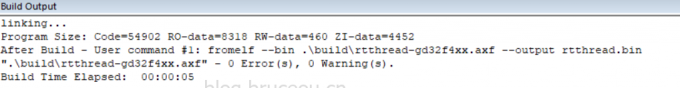
成功编译打印信息如下:
【注】笔者没有IAR环境,有兴趣的朋友自行去开发吧。
2.3使用GD-Link 下载调试GD32
前面使用ENV和MDK成功编译可BSP,那么接下来就是下载调试环节,下载需要下载器,而GD32部分开发板自带GD-link,可以用开发板上自带的GD-link调试仿真代码,不带的可外接GD-link模块,还是很方便的。具体操作方法如下。
1.第一次使用GD-link插入电脑后,会自动安装驱动。
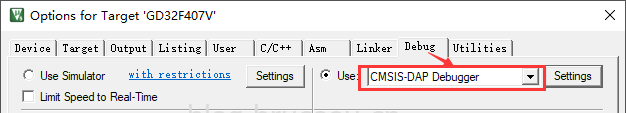
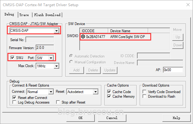
在Options for Target -> Debug 中选择“CMSIS-DAP Debugger”,值得注意的是,只有Keil4.74以上的版本和Keil5才支持CMSIS-DAP Debugger选项。
2.在Options for Target -> Debug ->Settings勾选SWJ、 Port选择 SW。右框IDcode会出现”0xXBAXXXXX”。
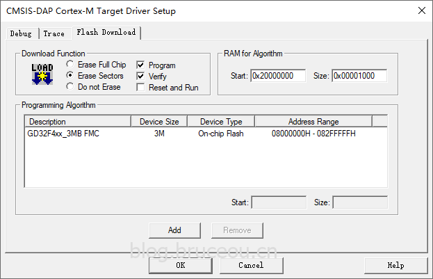
3.在Options for Target -> Debug ->Settings -> Flash Download中添加GD32的flash算法。
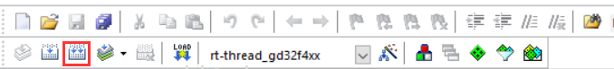
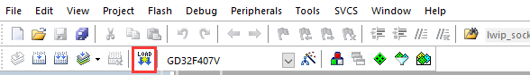
4.单击下图的快捷方式“debug”, 即可使用GD-Link进行仿真。
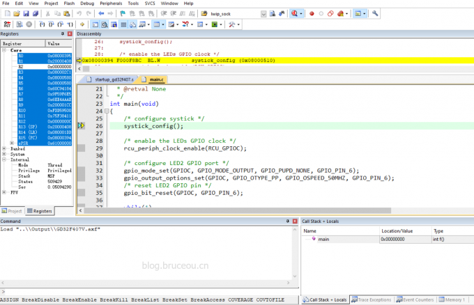
当然啦,也可使用GD-Link下载程序。
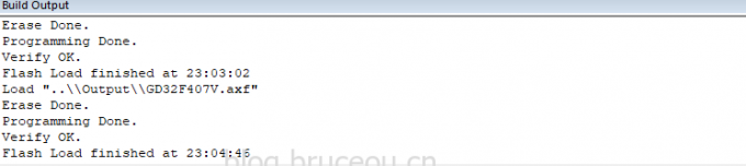
下载程序成功后,打印信息如下:
接上串口,打印信息如下:
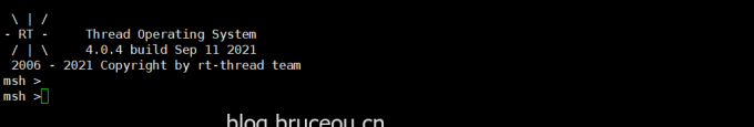
同时LED会不断闪烁。
2.4 RT-Thread studio开发
当然,该工程也可导出使用rt-thread studio开发。
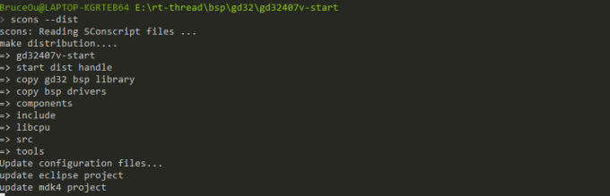
先使用scons --dist导出工程。
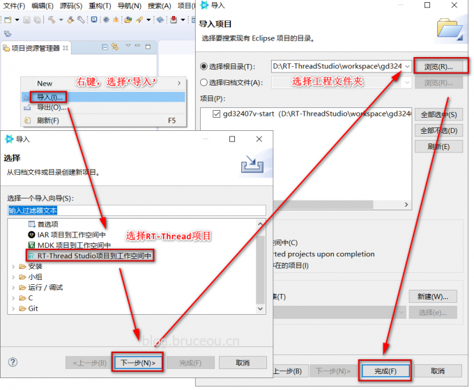
再将工程导入rt-thread studio中
最后,就可在rt-thread studio就可进行开发工作了。
当然啦,后面也可在rt-thread studio中新建工程时选择笔者提交的GD32407V-START的BSP。
关于BSP的移植就到这里了,当然还有很多内容,这里只是抛砖引玉。最后希望更多的朋友加入进来,为国产RTOS贡献自己的力量吧。